
النتائج 21 إلى 21 من 21
الموضوع: لاند روفر ديسكفري
-
LinkBack
 LinkBack URL
 About LinkBacks
- Bookmark & Share
- Tweet this thread
-

رقم العضوية : 24371
تاريخ التسجيل : 07Nov2008
المشاركات : 6,251
النوع : ذكر
الاقامة : القاهرة
السيارة: لايوجد
السيارة[2]: لايوجد
دراجة بخارية: لا يوجد
الحالة :

 -
hasad">Welcome to the Official Moe-Joe Cell WebsiteHow to Run the Car with the Moe-Joe Cell"Got my Moe-Joe Working!"
-
hasad">Welcome to the Official Moe-Joe Cell WebsiteHow to Run the Car with the Moe-Joe Cell"Got my Moe-Joe Working!"
Suggestions for How to Hook up the Moe-Joe Cell to the CarMoe-Joe Cell Car Installation Instructional VideoThese are other, complementary ideas and suggestions of how I have conceived of hooking the Moe-Joe up to the car. Here are some of the possibilities.
Practical Methods of Connecting to the Engine Theoretical Methods of Connecting to the Engine 1) To the Vacuum / Air Intake <<-- PREFERRED METHOD -Heart Engine Connection 2) To the Blind Plug (not much results with this method) 3) Just sitting in the Car, no direct connection (minor results)***IMPORTANT NOTE - For methods on assembly of the cells for the car - click here.***NOTE - On ALL car installations, place a 1.5 volt battery across the +ve and -ve of the cell to hold the potential when the car is running and also when it is not running.***Alternative Hookups, techniques1) The Topher "Dirt" Insulation technique 1) The Chris Felton "Moe-Joe Half Full" techniquePractical Methods of Connecting to the Engine1) Vacuum Air Intake Installation:
Sample Installation VIDEO using a Land Rover Discovery 2 year 2001 (Moshe's Installation)
Sample Installation VIDEO using a Honda Accord year 2001 (Moshe's Installation)
Sample Car Installation Video with Land Rover Discovery II 2001, Moe-Joe Cell
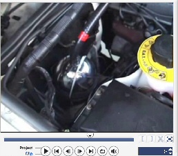 This Video Contains instructions on how to assemble the Moe-Joe Cell and Install into the Car via VACUUM intake, and also demonstrates how to get under the car and locate the catalytic converter and the O2 sensors. (note: in this video, we chose a method we are no longer employing the use of - We hooked the two rear O2 sensors together and then we also hooked up the front two O2 sensors together - Also, we are no longer using the Cell Guardian. It DOES NOT WORK - it is a scam. We are sorry if this has misled anyone. The good results we got were exclusively from the Moe-Joe working, and NOT the Cell Guardian... click here for more on this).Note: With the vacuum air intake connection, the best idea to connect the Moe-Joe cell is where the water level is at exactly HALFWAY, so the Moe-Joe is half-full AND it is half empty. This creates an important Vacuum pressure in the cell itself. Thanks to Chris Felton for this important improvement. Click here for instructions on the HALF CELL ASSEMBLY.Short Sample Car Installation Video with Honda Accord 2001, Moe-Joe Cell
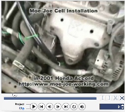 Honda Accord 2001This short video demonstrates a Moe-Joe cell installed in a 2001 Honda Accord right in between the radiator fans and the exhaust. The cell stayed cool to the touch. note: in this video, we chose a method we are no longer employing the use of - We hooked the two rear O2 sensors together and then we also hooked up the front two O2 sensors together - Also, we are no longer using the Cell Guardian. It DOES NOT WORK - it is a scam. We are sorry if this has misled anyone. The good results we got were exclusively from the Moe-Joe working, and NOT the Cell Guardian... click here for more on this.2) Blind Plug Connection:
Charge enough water to stage 3 using a Moe-Joe cell and place it into a Moe-Joe ready for installation into the car. Secure the Moe-Joe well, using rubber or some very well insulated material. Do not allow any part of the outer sphere to contact the chassis.
The cathode bolt that is coming out of the top of the outer sphere, that is connected electrically both with the central bismuth core and the inner 2" sphere, will be sticking out slightly. Connect a wire to the end of this cathode bolt and shrink wrap it or tape with electrical tape - sealing any exposure of the metal to the air or any water it can contact. The length of the wire should be measured to be able to follow along the inside of the aluminum transfer tube and end at the engine block (for a blind plug connection) or some metallic component connected to the engine block.
As seen in this picture on the right, this is an aluminum transfer tube, which an air-tight and water proof layer of PVC outside. The wire coming from the inside of the inner sphere, carrying the female energy and the neutral centre (what does this mean? - click here for some discussions on the theory behind the functioning of the Moe-Joe cell) will be brought to the engine through the inside of transfer tube. The aluminum of the tube should be contacting the outer sphere, and thus carrying the male.
 The female is carried by the wire to the engine block and should have an electrical connection right onto the engine block. The ending of the aluminum tube should not contact the engine block, and so some of the aluminum should be cut out at the end, to ensure that the PVC contacts the engine block and not the aluminum (which would short out the cell, since the ally tube is connected electrically to the outer sphere which will be charged with positive electricity from the battery)
With this blind plug option, DO NOT seal for AIR tightness the end of the ally tube where it meets the engine... gasses can accumulate in the transfer tube and cause an explosion. Just fix it to the engine block / head so that it doesn't move around and make sure it is not sealed tight, to allow the small amount of gas to leak out and not build up.
3) Simple Low-Maintenance Connection Method - Just Sit the Cell in the Car somewhere: The possibility is that the cell will run the car just by being charged to stage 3 and then hooking the cell cathode to the centre sphere to the negative of the battery. And then the positive electricity from the battery can be applied briefly to the outer sphere. This can be done with or without a transfer tube. It is possible that this may have an effect on engine performance, as there have been observations within the Joe Cell field of cells affecting engine performance just by sitting in the car, not even hooked up to the engine or battery.
There are probably superior ways to get the moe-joe working with the engine. This technology will be constantly evolving, and that's a good thing for all of us. If you have some ideas, especially if they are tried and tested, please email them to me here.
Whether or not this will, in fact, run a car, remains to be seen - but i think i'd like to see the Moe-Joe in many hands, and many people getting the success with it. Intuitively, i know it works. It is quite amazing. I also am sure that all the folk out there who have already ordered the moe-joes, will be helping me improve it for everyone.
Theoretical Connection (Untried Theory / Idea)1) The Heart Engine
Right now, I feel this is the most powerful and "sensical" one is The Heart Engine. What a beautiful design!! This is only theoretical for now...
Introducing the Heart Engine by Moshe DanielThis design involves the integration of four different and very special technologies, with the main technology still featured around the Joe Cell / Moe-Joe cell. Some of the exact details of how to do so need to be advanced further and clarified – what is required is experimentation and some modifications to the car. Amazingly, the Heart Engine also functions alot like our very own Circulatory System - Hence called The Heart Engine.
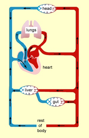 Our Circulatory SystemThe FOUR different technologies applied are:
John Keely’s water cavitation engine
Lord Kelvin Electrostatic high voltage generator
The GEET engine
The Joe / Moe-Joe cell
1. Charge a large amount of water to stage 3 using charging plates ala Bernie or Joe, or using your regular Joe cell or Moe-Joe cell as a charged.
2.Install the Joe / Moe-Joe cell lying down horizontally in the engine compartment (here’s where the Moe-Joe is easier to do this with – it’s smaller). Isolate the entire cell electrically from the chassis (although there is an electrical connection to the inner tube). Apply a tube (ideally the tube seen here – which is an aluminum tube which water-tight PVC exterior) to the top – or out end of the Joe Cell – this transfer tube is going to be brought right to the intake of the pistons. (I don’t understand car mechanics that well, so I am just writing approximately – details to be worked out later) – this connection has to be SEALED – water tight and air tight. This transfer tube that is connected electrically with the inner tube or sphere, is connected electrically to the engine block – right where it connects and is sealed to the engine intake at the piston opening. So basically, here, the transfer tube to the engine will replace and follow the fuel line. Note: It is possible that this whole thing may work better with just the electrostatic generation as described in #4. In which case, the transfer tube should be isolated from the engine block, but still sealed to the moe-joe out and the engine input.
3. GEET aspect: Connect another transfer tube on the exhaust of the engine – that is, the space leaving the pistons – as close as possible to the engine – and engineer this tube to be electrically insulated from the engine block – but sealed for air and water tightness. No leaks!! Engineer this tube now to perform in the fashion of the GEET engine – that is – the outflow from the exhaust will be brought to SURROUND the transfer tube from the cell to the engine. This will create a vortexing of opposite magnetic energy. Now, after the exhaust line follows over the inner tube going to the engine, it will turn and go into the bottom of the cell – which has an open connection – and an electric connection to the outer sphere / cylinder of the cell. This completes the circulation aspect, resembling the functioning of a heart – and the high voltage ignition coil is like the pacemaker of the heart.
4. Lord Kelvin’s Electrostatic generator aspect: now, at the point where the exhaust tube is over and surrounding the inner transfer tube, could be set up with dissimilar metals at least for the portion that is intersecting at least 1 – 2 feet, with a minimum preferred at 18”. Aluminum for the transfer from the inner pipe / sphere and to the engine and copper for the outer one. The dissimilar metals could an increased electrostatic potential difference in the water charge. This can keep the water in the cell continuously charged while the car is running. It may also influence the voltage at the point of ignition. It is possible that this system can create much more energy than it is using.
5. Keely’s cavitational water flow system – By having the flow of water through a pipe suddenly cut off, on the side of the cutoff, that is, where there was water flowing, now there is not, this causes a cavitation. This will occur in the pistons, when the intake, which ordinarily would take in a mixture of air and fuel, will take in ONLY the charged water which will fill this entire circulatory system – like a beautiful giant heart – this will add to the power of the cavitation – and also, the mist that will be brought into the pistons will also cavitate back to the state of water, and will flow out of the exhaust, and back into the circulatory system.
6. Fill the entire Moe-Joe / Joe cell with charged water. Make sure the water fills all the way from the cell and fills both transfer tubes, but no water at all enters into the pistons… yet. The pistons should remain “empty” or vacuumed. To do so, have a hole made into one of the transfer tubes and fill it up from there – completely… measure the total volume outside of the car, and then fill with this amount. Make sure pistons are closed tightly while filling.
Additional notes:
This should work! I know it seems crazy – but all that is needed will be a clean engine with no gasoline in it. Ideally, a brand new engine, that has not even been tested with gasoline, so that it is pristine… brand, brand new. with nice pure good Stage 3 water.
Also, when the charged water goes into the pistons, it will give up its energy – and so when it is back in the circulatory system, in the exhaust aspect, it will become recharged, with high electrostatic energy. The water will also become recharged by flowing back into the moe-joe… and anyway, the water is ONE within itself, within the Heart Engine.
It may be necessary to hand crank this engine, as Keely’s motor required, in order to get the flow starting.
Possible related article – firing of high voltage spark under water - http://www.iop.org/EJ/abstract/0022-3727/39/22/011 - with the Heart Motor, it won’t be underwater though.
The engine should run cold.
Use of the engine that has been dirtied with fuel –
Run the car down to almost empty – then drain all the fuel from the fuel line and in the engine. Clean out.
How the pressure be discharged in a closed loop system?
I don’t think this is necessary – since it will a continual implosive force, and won’t build outward, but may build somehow inward and hopefully stabilize at a certain point.
<<Notes on Lord Kelvin’s Electrostatic Generator –
From High voltage device: Kelvin's Thunderstorm
THE BASIC THEORY
Even though water has no overall electric charge, it is full of movable electric charges (called ions). Half of the water's charges are positive and half are negative. It is not hard to separate these charges; simply hold an electrified object near the water. The electrified object will attract the "unlike" charges to the water's surface. It will also repel the "alike" charges away deeper into the water.
In the above diagram, the positive object attracts the water's negative ions and repels the positive ions. This draws an excess of negative ions into the tip of the water dripper, while repelling an equal amount of positive ions off to the other end of the dripper. When the water drop detaches from the tip of the dripper, an overall negative electric charge is still trapped in the droplet. The falling water droplet carries away negative charge, leaving the dripper slightly positive. If we catch the falling droplets in a container, the container will become negatively charged.
In the above diagram, negative water droplets will be continuously created forever as long as the water flows. However, this process does not exhaust the imbalanced charge on the positive object. Sounds like perpetual motion, eh? Actually no. The electrical energy is being created by the work that gravity does in pulling the negative droplet away from the grounded dripper, and away against the attraction of the positive object. The electrical attraction force from the positively-charged object keeps the tip of the dripper charged negatively, but the positively charged object does not supply energy. YOU supply the energy, since you LIFT the water to a height to fill the dripper. It's like the generator in a hydroelectric dam, but without the turbine or the spinning coils or magnets. The water itself becomes the moving parts of an electric generator.
(Note: the charge polarities can easily be reversed. If the above "object" is made negative, the droplets would come out positive.)
BUILDING A GENERATOR
If we can make a positively-charged object somehow, then we can make negative water droplets. But where can we get a positive object? If there was some way to CHANGE the negative charge on the water into a positive charge, then we could use the water to charge up it's own "positive object". We would then have a a self-sustaining generator. There's a simple way to do this: build TWO water-drop devices like the one in figure one! See the trick? The device in figure one uses a positive object to create negative water. It uses positive to create negative. If we build a second device, we could use the negative to create positive. We could hook the two devices in a loop. The first one would create an imbalance of negative charge, which could be fed to the second one which would create an imbalance of positive charge, which would be fed back to the first one again. It might sound crazy, but it really works. >>>
That is exactly what we’re doing – creating a loop where the intake line is charged negatively, and the positive line will / can be charged positively. Wow!! This is a free energy device if ever one was created. The continual flow of water will create a continual electrostatic high voltage generation with an even greater potential difference than with just ONE electrostatic generator – which possibly can be fed back into the flow of the high voltage ignition coil.
The negative electrostatic potential will be feeding the inner cylinder / sphere with negative potential and the outer tube will be feeding the outer sphere / cylinder with positive – keeping the water within the cell, at the zero point between them charged with our magic.
Modifications to Car Needed –
- Disconnected the fuel line from the gas tank and connect / engineer to connect with the transfer tube coming from the output of the cell. The fuel pumps will be pushing the water through and into the pistons – from the cell and NOT from the gas tank.
- Disconnect the O2 sensors / modify the computer to be able to function independently of the O2 sensors. (I am not certain exactly how to describe this)
3) For some possible stage 4 effects, one could find a way of using the power of the ignition coil in the car to charge the cell on that very high voltage. If you have any ideas of how this can be done, ie - using the ignition coil as the power supply to the cell, please email them to me here.
Topher's Dirt Insulation TechniqueMy friend Topher came up with an ingenious way to insulate the Moe-Joe cell inside the hot engine compartment. Basically, he took two rubber gaskets, (one of which is seen, in the first video, on the installation in the Land Rover) - he put the Moe-Joe cell in the gaskets, which are placed together with their bottoms facing in opposite directions, and then filled the space inside the gaskets with earth, mud, dirt. This is an amazingly simple and easy solution to provide heat shielding in a hot engine compartment - the cell stays cool, and with this technique, the Land Rover went from 12.1 MPG to 17.5 MPG.
Chris Felton's Moe-Joe Half Full or (Half Empty) TechniqueChris Felton suggested, that for VACUUM intake, or Air intake hookups, that the moe-joe cell will perform much better if the cell is only filled halfway, as the pressure on the vacuum or air intake has no way of acting if the cell is filled. For the blind plug technique, however, it is important to keep the cell filled to the brim.
All Contents Copyright © 2003-2009 Moshe Daniel Block, N.D.
All rights reserved.Revised: This page was last modified Tuesday, August 23, 2011.

 رد مع اقتباس
المواضيع المتشابهه
-
لاند روفر تحتفل بالعيد ال40 لرانج روفر برائعتها الجديدة Evque
بواسطة aly_hosny في المنتدى أخبار السيارات في مصر والعالممشاركات: 4آخر مشاركة: 23-09-2010, 03:22 AM -
جيب لاند روفر كونسبت الجديد
بواسطة MoOoON في المنتدى الأمـــريكى العـــاممشاركات: 6آخر مشاركة: 06-08-2010, 11:30 AM -
لاند روفر ديسكفرى 98
بواسطة tech_moh في المنتدى قسم سيارت الدفع الرباعى وال SUVمشاركات: 12آخر مشاركة: 12-06-2010, 10:34 PM -
لاند روفر 96
بواسطة link7200 في المنتدى الأوروبـــى العـــــاممشاركات: 14آخر مشاركة: 01-12-2009, 08:47 AM -
لاند روفر فريلاندر الجديدة
بواسطة Sharky في المنتدى قسم سيارت الدفع الرباعى وال SUVمشاركات: 0آخر مشاركة: 04-05-2007, 12:23 AM
الكلمات الدلالية لهذا الموضوع
20,
40,
50,
ملاك,
لادا,
لاند,
مرور,
مشاكل,
مصر,
مع,
معلومات,
من,
موتور,
موديل,
التوكيل,
الي,
الشنطة,
اداء,
اركب,
اسعار,
اسعار قطع الغيار,
اوتوماتيك,
تيل,
تيل فرامل,
تجديد,
تريوس,
تغيير,
بنزين,
تقييم,
تكييف,
دى,
ديسكفري,
ريو,
روفر,
سمكره,
صالون,
شار,
سيارات,
سيارة,
صيانات,
زيت,
سير,
سعر,
tiggo,
عايز,
غيار,
عربيه,
عن,
فلتر,
فلتر بنزين,
فلتر هواء,
فتيس,
في,
فرامل,
فرش,
هل,
هي,
نيف,
نيفا,
نيو,
ورشة,
قطع,
قطع الغيار,
قطع غيار,
كل,
كروزر
 ضوابط المشاركة
Content Relevant URLs by vBSEO 3.6.0 PL2
المفضلات